Startup: Catalyst Frame Microscope Part4 - Manufacturing... There be Dragons

catalystframe.com
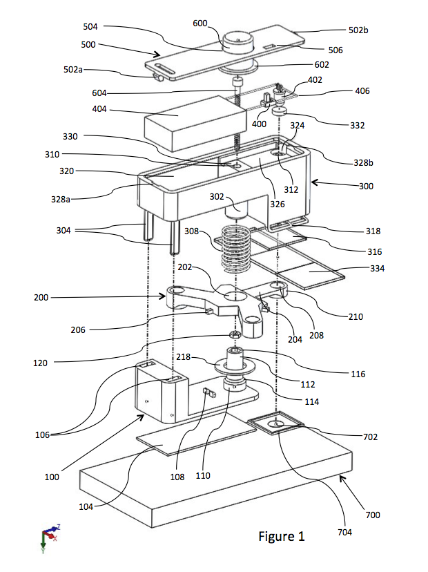
Bill of materials
First we start with a bill of materials, which is basically a break-down of all the components you'll need to put together the product. Here's a simplified version for the time being:
Plastic microscope upper frame
Plastic microscope lower frame
Variable resistance potentiometer
LED
2 AAA battery contacts
Electrical wiring
Spring
Clip
Acrylic stage cover
Plastic 3-way lens frame
Laser focusing lens
2mm ball lens
2mm ball lens holder
1mm ball lens
1mm ball lens holder
Lid
Knob
Center support screw
2 Lid screws
2 Clip screws
5 Threaded press inserts
Re-stickable adhesive
Acrylic microscope stand
Silicon glue
Solder
Now how do you want to procure these components? Well there's buying it off-the-shelf, out-sourcing for a custom component, or in-house production of a custom component. And it's a balancing act between these options and the design you're using.
If you can tweak your design a little bit to use something off-the-shelf, do that first. Obviously this is easier said than done, because often times you'll need to make certain sacrifices. And one of the real kickers I found out about trying to build a compact device is that there aren't a lot of off-the-shelf components you can use without blowing up the product dimensions/design.
So for the custom components what do we do?
One may think well if I vertically integrate and handle all production in-house, I'll be able to maintain a higher profit margin. But that's not always true, you will likely be less efficient than someone whose specializing and has all the necessary equipment setup to produce said component. That inefficiency means it'll take you more time, and time isn't free there's always at least an opportunity cost. Therefore if you're smaller it's overall better to avoid in-house production as much as possible, since you probably won't have the capability.
And at the same time, sometimes you don't have a choice. You have a budget, there's something you need to do, and sometimes you gotta just bite the bullet.
So after looking for all the components I needed, I eventually got something like this for off the shelf components (this one includes various manufacturing materials as well):

This document specifically shows where I'm going the buy the component and exactly which component. Of course, this is after I've already bought a few sample components and tried it out in the design to make sure everything works as intended.
But there's obviously plenty of components I couldn't just buy from a store or it was getting difficult to find the right one.
Plastic microscope upper frame
Plastic microscope lower frame
Spring
Clip
Acrylic stage cover
Plastic 3-way lens frame
2mm ball lens holder
1mm ball lens holder
Lid
Knob
Acrylic microscope stand
Luckily there are places like TechShop that let's you use all sorts of equipment and tools for a relatively low monthly cost. And here's what happened.
Injection molding
So originally I wanted to use injection molding for the main upper and lower frame. I went down the road of trying to use the TechShop tools to setup for some injection molds, but it was frustrating. One of the most disappointing things was trying to convert the CAD into CAM, which are the CNC instructions. What happened was the Techshop computers with the $1000+ CAM software were so slow and frankly screwed up that it crashed every time I tried to output the CAM instructions. So I gave up on that idea pretty quickly.
Then I went to Protolabs to get a quote for the main parts. They have a great interface to help you make sure you get what you expected from the injection molding process. For instance, making sure your part is slightly chamfered in any pocket areas to allow easy separation of the part from the mold or dealing with shrinkage from thick areas.
However, the main problem with going down that route was what would happen if I needed to change the design when the two molds for the upper and lower frame costed $7000. Plus this kind of injection molding has a tolerance of around 1-2mm, would the design be able to handle that when I need to hold a 0.47 mm gap?
On top of that, there was still a problem with the microscope that I wanted to fix. Remember how a focused image required that the lens be 0.47mm away from the sample? Well I was able to get that, but only if I didn't shake the microscope around. There was enough slop in the center guide rod that if I shook the microscope around a little, it made the image come in and out of focus.
So I needed to do some more prototyping, and my last prototype printed by Stratasys costed $300, which meant I needed to buy a 3D printer.
3D Printing for prototyping and manufacture
Overall, I settled on the Form1+ it seemed to have the best print performance for it's cost of $3500 at the time. And I put it to work immediately to try to fix this wobble issue in the center guide rods.

It took about a couple weeks to finally figure out the answer. At first I tried just machining higher precision parts, but it wouldn't have been a good solution. I had to cut aluminum stock rods into shorter lengths, smooth the ends, and bore out the center hole. It was a much more involved process and I was about to look into ordering these parts until I realized the 'first principles' of the problem.
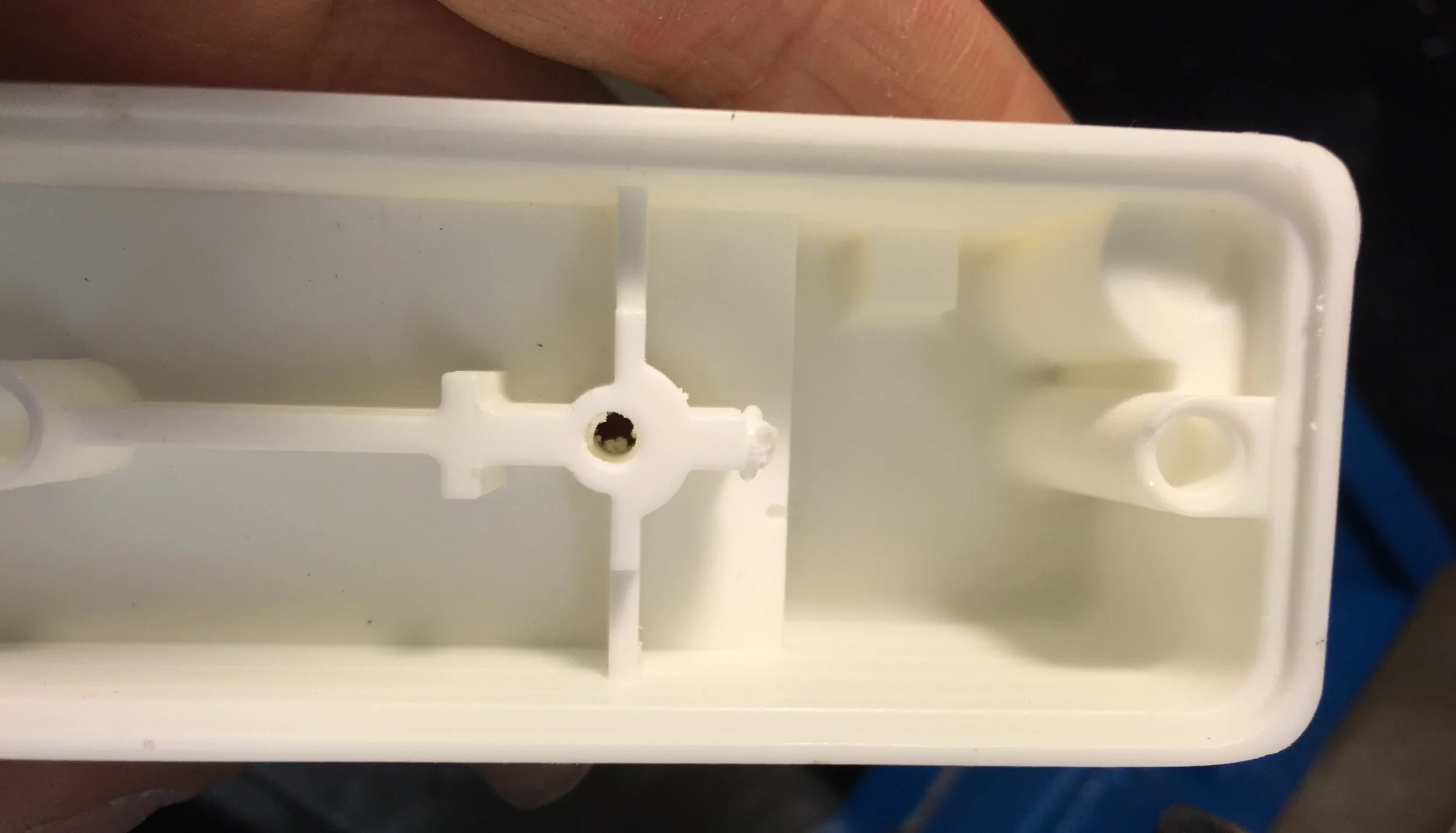
What I realized was that my current design was relying too much on the tolerances of the center guide rod for all the precision, and it was impossible to get these plastic components down to the precision necessary without resorting to some kind of expensive injection molding, QA processes, or using custom machined parts. But what if I used something that was already very precise, the center screw that drives the stage up and down? With my old design I had only one threaded press insert for driving the stage, but if I used two spaced threaded inserts it would help reduce the wobble.


In addition, I realized I could crimp the threaded press inserts and then put glue around press insert before putting it into the plastic part. Then before the glue set, run the screw through it, expanding the press insert to exactly the diameter of the screw, and then the cured glue will provide a backing to maintain the dimensions.
Now it's extremely stable, because we've essentially squeezed all the tolerances, and now it's like this.

After trying out a microscope with the new design, it held 0.47mm like a boss! Okay one problem solved back to figuring out how to mass manufacture the plastic components.
3D Printing is a fantastic tool that has just recently become cheap enough and good enough to be used for production. It can handle much more complicated geometries than injection molding or even CNCing. Per part it's more expensive than injection molding, but less than getting it CNC'd. And you can make changes on the fly, so it's fantastic for prototyping or changes to the manufactured part.
However, it doesn't come without drawbacks. The main issue is dealing with larger parts. First off most 3D printers have a fairly limited build volume. Secondly 3D printing for the most part is a slow process. To give an example, printing a coffee mug would take most of the Form1+ build volume and take about 5-6 hours at it's fastest setting.
Now after using the 3D printer for prototyping, I had hoped to potentially 3D print out all the main plastic components even printing the clip into the frame. In terms of material cost and print time, it seemed like it'd work. And in fact, this is part of how I had priced the Kickstarter rewards with the idea that this would be my ultimate fallback manufacturing strategy.
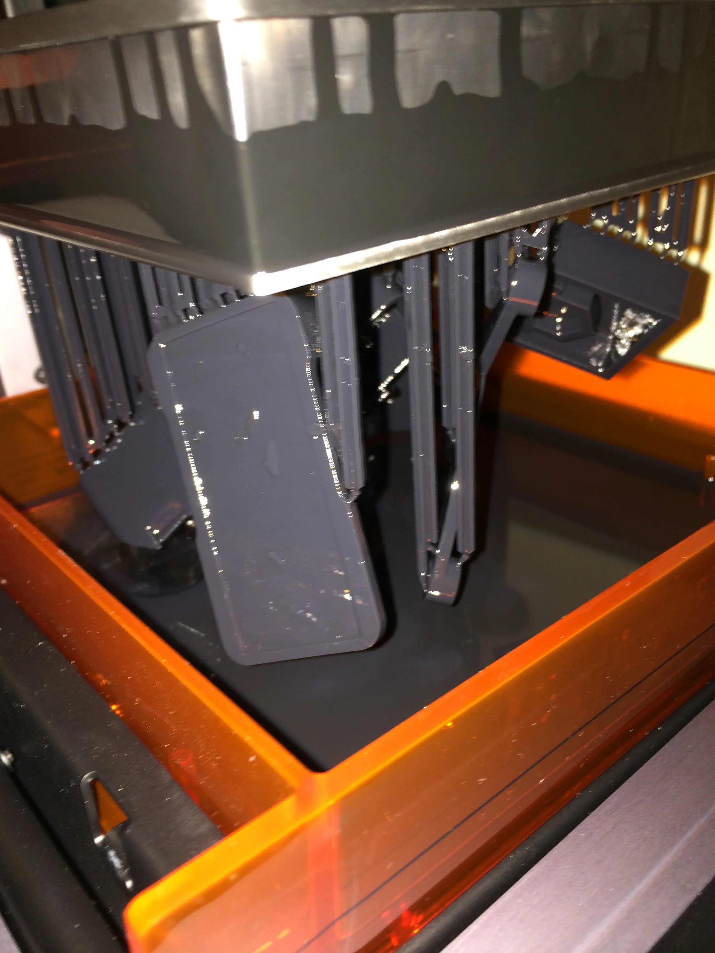
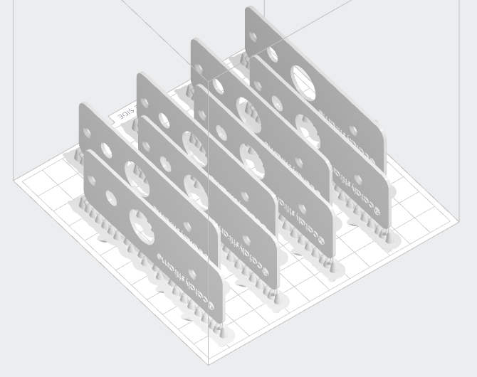
Unfortunately only after using it more I found out that the print needs to be printed at an angle and cannot handle enclosed hollow areas (details not explained on the printer manufacture website at the time). So due to the geometry of the main upper and lower frames plus these restrictions it needs to be printed in a way that leaves the parts covered in support structures that take up a lot more material, time to remove, even more time to finish polishing the part surface, and reduces output per batch.
Also printing out thin walled structures tended to warp especially during the post-cure process, so the 3-way lens frame would come out completely unusable.
And the final cherry on top was that it was impossible to track what parts of the resin tank were being overused. Once a part of the resin tank is too degraded, the cured resin may stick to the tank side rather than the part. This speck of stuck resin will slowly grow with successive layers and completely destroy your print, and also accelerate damage of the resin tank.
So that was a big problem, this is after I had already been funded and spent a decent chunk trying to build it, so there's no turning back. I needed to come up with another solution. So I got online and started researching, and in the meantime I did what I could with the 3D printer.
So where a 3D printer really shines for manufacturing is for making smaller custom parts. Before you would need to either mold or CNC the parts, both of which are expensive. It'd be crazy because just a small part can cost you a small fortune. Now you can just print them out in mass for less than a dollar each.
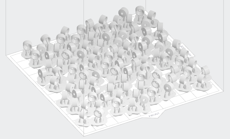
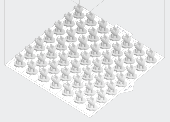
Per run, I got about 15 knobs, ~50 ball lens holders, 8 lids, or 49 center guide rod spacers. And I think all the 3D printed parts for 250 microscopes costed around $450.
Resin Casting
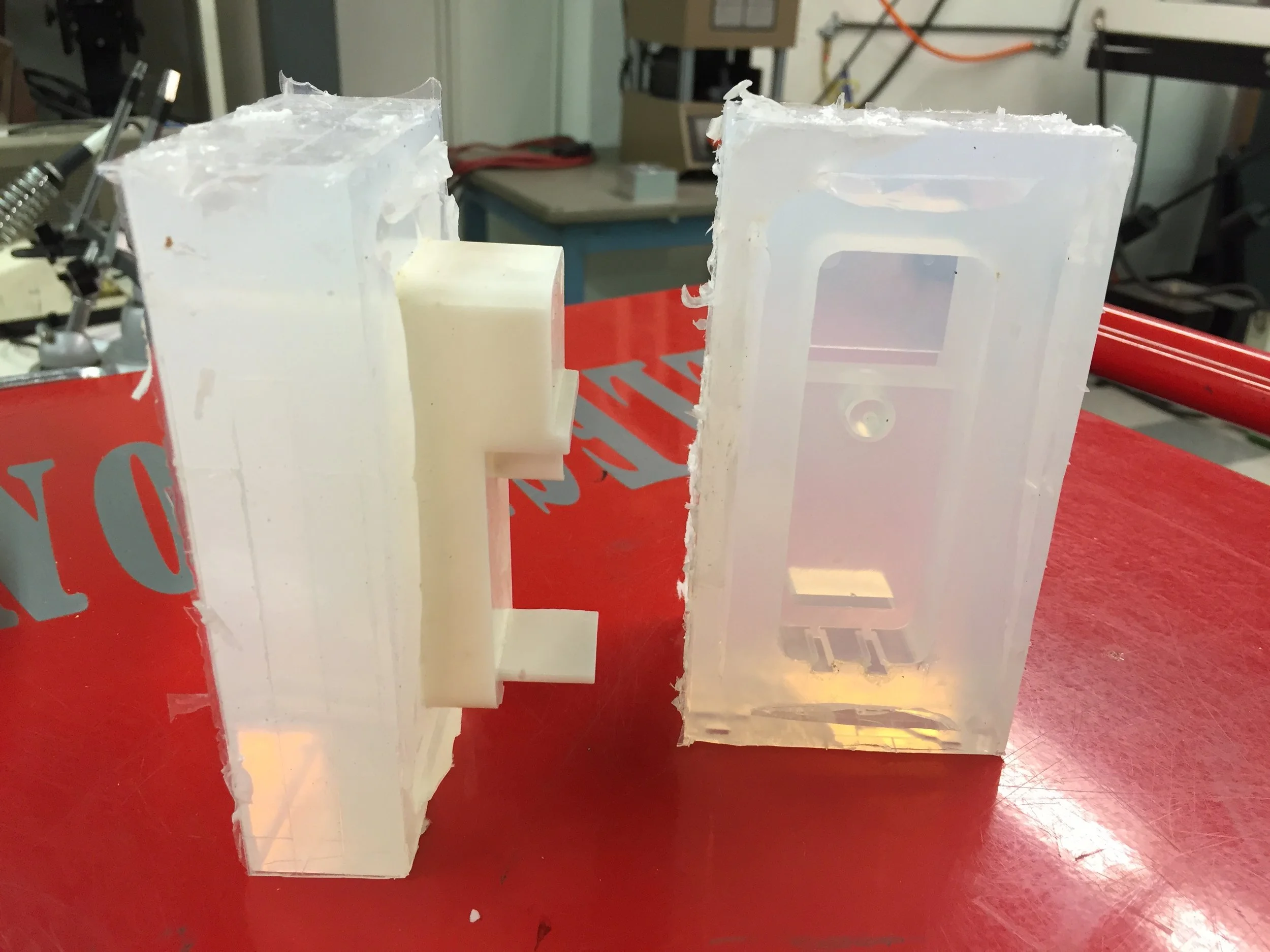
So I was still stuck on how to manufacture the main parts to the microscope but I was looking into various prototyping/manufacturing technologies and eventually discovered resin casting. It's a technology that can be used to produce short runs of parts think 10-50 parts per mold depending on the geometry. Basically you make a silicone mold with a feed line into the mold, and vent holes to allow air to escape. Then a liquid resin is injected into the mold allowing it to cure. Then the mold is disassembled and the part removed.
It's definitely a much more labor intensive process, but the test run showed incredible results. It was also economically feasible, since the the silicon, resin, and equipment were relatively inexpensive. Finally, the process was fast enough for production.
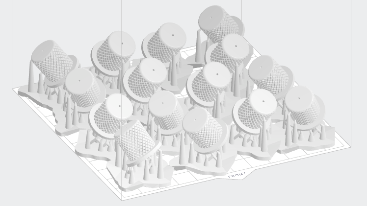
After that I ordered the master patterns from Stratasys to be printed with a high quality polyjet printer so that I could start making the production molds.
In the meantime, I 3D printed out feed lines and vents. These prints contain a chemical that inhibit platinum based silicone curing and need to be sealed with an acrylic coat, which you can get in a spray can.

Some tips when it comes to resin casting are:
If you're doing a two-part mold, don't forget to use something to create guide features to align the two halves. I used capped metal nuts, which are nice since they don't float.
Best feed lines/vents with a small tip, so that you have less flash to remove.
You can use hot glue to temporarily glue the feed lines and vents to the master pattern.
Use a vacuum chamber and vacuum pump to remove air bubbles from your silicone and resin after mixing but prior to use
Fill the mold at an angle that allows the resin to flow into the mold while pushing air out. So the feed line should be close to the bottom of the mold.
If you're using a two-part mold, make sure to use rubber bands or something to help keep the two halves from separating. I discovered this problem when some parts had excessive flash, which also meant severely skewed dimensions.
Use a pressure vessel to apply air pressure once the mold is filled, this will greatly help reduce any remaining air bubbles. We used a converted pressure paint pot from Harbor Freight and ran 30PSI with decent results (occasional air bubbles around the edges of the parts). If you have the resources to buy a real pressure vessel, you'll be able to safely run higher pressure and get consistently perfect results.
Allow sufficient time for the resin to cure before removing from the mold. The manufacture provided a cure time of about an hour, but in practice we discovered it needs another half an hour before it's cured enough to be removed from the mold. We found earlier runs produced warped parts, because we were trying to maximize output.
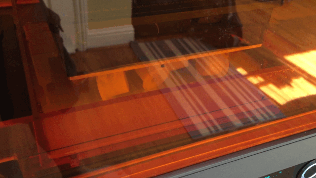
Here's a picture of our setup:

Unfortunately after I had made the production molds, I discovered there was a really weird print defect in my part. One of the railings was nearly 0.7mm thicker than it was supposed to be, you can pretty much see the difference. Luckily it was a feature on the part that wasn't essential, it was meant to be a potential mounting point for custom phone cases that allowed easier mounting of the microscope to the phone.

So a word of caution even though there shouldn't be any problems, always double check.
Alright so now we're spitting out parts:

Are we done? Noooooooooooope! These parts need to be polished to remove the flash and are missing the holes for the LED light, the center guide rod screw, and the holes for the clip. Can't really do these holes with the mold, because it'll reduce the mold lifespan and as a flexible rubber aren't stable enough. But I did use the mold to create the threaded press insert holes for the lid screws, since these were short and stubby.
So basically I 3D printed out a ton of jigs that fit over the part, and allowed me to center the drill press into exactly the right location. While the part itself was in another simple jig (just some backing elements) that allowed me to slot in a next part. If the part wasn't centered properly, the drill bit would clearly cut into the jig. Generally I would put those slightly off-centered ones aside to be machined afterwards together.

And one of the first completed microscopes with this process.

Now that I was finally churning out the main plastic components, I turned my attention to the other parts.
Laser Cutting
Out of all the manufacturing technologies, I have to admit laser cutting is one of the fastest, cheapest, and most accessible. And when used properly, you can build a lot with it. For example, the original Makerbot's frame was laser-cut plywood.
Now not everything can be laser cut though. Certain materials catch fire too easily and will just burst into flames, while others can release toxic and carcinogenic fumes. Also the thickness and type of material is somewhat limited, you need to be able to burn through it, so probably won't be cutting through metal or ceramics. Also the thicker the material, the more of a chamfer (or slanted edge) you'll get on the part due to the focusing of the laser.
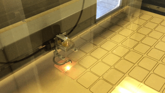
But we will be using the laser cutter to produce the acrylic stage covers and acrylic microscope stand. For all 250 microscopes, I used about 5 sheets like the one above for about $25 each and it took overall about a day at the Techshop.

Outsourcing
Now there's still some custom components that are very difficult to make without the proper equipment. I needed a custom spring which helps stabilizes the stage and a custom clip to hold the microscope slides.
The spring I needed custom, because there were so many requirements. If it's too narrow, it won't fit around the guide rod. If it's too wide, it'll collide with the frame. Also it needs to be able to provide a reasonable force when the microscope stage is fully extended and collapsed, while being able to compress without bulging in any direction.
Luckily I was able to get the custom springs made for a moderate amount more than what it would've costed to buy from the store, so about $2.50 per custom spring compared to $1.50 per store-bought spring. I also looked into having the same company make the clips, but they didn't handle that type of work.
Waterjet Cutting
The clips needed to be screwed down into the microscope frame and bent over the stage. So I decided to make those myself, since it looked easy enough. Ha! It was a bit harder than I thought.
Either way, I bought some sheets of spring steel online. And optimized the cutting path for as much continuous cutting as possible, since the longest step is the starting/stopping of the waterjet. I tried a small run with the clip at different dimensions to see what worked best. Once I had that I switched to making the batch run.
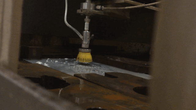
My mistake was how long post processing would take. The waterjet cutting produces a blasted out rough edge on the other side the sheet metal and it took forever to sand that edge down. It's steel and tough, so it's a slow process to begin with. But since I was sanding hundreds of rough edges, it'd also wear down the sanding pad extremely quickly. It took a lot more time and I used a lot more sanding pads than I thought I'd use.
Then came making a jig to bend it into the right shape. It kind of worked, but since it was so small, it difficult to manipulate properly. At the end of the day, it got the job done.
Assembly - it takes forever...

If there was one thing that I have to say I really underestimated was how much time it took to put everything together. It almost feels like it's an exponential increase in time for a linear increase in production volume. In reality it wasn't, but it was slow.
Assembly is definitely another area of design for manufacture. For instance, if we could just plug together electrical connections rather than having to cut, strip, and solder everything together, it would have been an order of magnitude faster.
I'll spare you all the gory details about all the little steps to produce this microscope, but all the little steps add up quickly.
This is where it's really important know ahead of time how exactly are you going to manufacture this. So that you can time out how long it takes before you price out your product, so that you can properly account for the labor time.
Hour, days, weeks, months later, we're getting there.


Packaging
Oh yeah packaging doesn't figure itself out for you. I needed to ship out a relatively delicate microscope around the world without paying an arm and a leg for shipping. In the end, I used bubble wrap, which was folded, layered, and taped into a sphere of protection.
And I tested it by putting a working microscope into a box. Then proceeding to kick, throw, and body slam it until I was satisfied that I had gone above and beyond what it could run into through its international journey. And then checked if it still worked. It was good!
Quality Control and Assurance

Now quality control isn't really at the end. It was happening at every step of the way.
The parts for the microscopes were made in batches of about 25 initially and then ramping up to 50. This let me troubleshoot any manufacturing problems that I discovered before it was something I had to fix 250 times...
And we found various issues:
We found that the super glue used to glue down the battery contacts would actually cause fogging on the lens outside. So we switched to using the silicone glue for almost everything on the microscope.
It turned out that some of the 3D printed parts still had some uncured surfaces. This was especially the case with the inside of the knobs, so we had to leave them out in the sun for an extended period of time to complete the cure.
We found out that clip was interfering with the stage coming all the way down, it was acting like a jack. And luckily we were able to fix it by moving the clip to a lower position (since it had a slotted screw hole) and bending it so that it applied the appropriate pressure to hold a microscope slide.
We found that one of the molds for the 3-way lens frame was warped. And eventually pinpointed the particular mold in the production mold and avoided using it.
We found that the mold release from the resin casting process was still all over the parts and making it difficult for glue to adhere. So we needed to wash them in soap before using them.
At one point, I had to temporarily move production back home in Sacramento. It was winter and I was working in my garage. However, what was interesting was that the parts seemed more brittle than usual. After thinking about it, I had realized that the extreme cold was inhibiting the chemical reaction in the resin. So I brought in some heaters and got the temperature up, and then the parts came out properly.
Now the final thing necessary to clear a microscope to be ready for deliver was testing it. This was an extremely time consuming step, because it involved mounting the microscope to the smartphone, putting in a slide, and getting a clear focused image for each lens.
But by running these tests, we can continue to look for any problems and deal with them before they were put into a customers hands. We found things like:
The knob was extremely difficult to turn. Generally we swapped out the base frame.
The light didn't work. We checked the soldering and sometimes replaced the potentiometer. Since the original potentiometer's metal knob was way too long, it needed to be cut and ground down, which sometimes heated up the part till it broke.
The lens was heavily mis-aligned from lens to lens.
Being unknown unknowns, this stuff can't be predicted, you just have to spend time testing it.
That being said, this could have been more efficient. Instead of fully testing every microscope, spend enough time testing to learn what problems generally come up, and then find efficient ways for testing those problems. For instance to test for a mis-aligned lens, I could've removed the smartphone and looked at the projection of the lens on a wall, and been able to figure out if there's a problem much more quickly.
And this is where design for manufacture plays another role is having quick and easy ways to do QA/QC.
Wrap-Up
Now having an accurate cost to manufacture/delivery means understanding all the above and more, so exactly how each component is going to be procured/manufactured in terms of cost and time, including assembly time, parts lost due to manufacturing defects, packaging, and shipping. This is why hardware is hard. All this stuff needs to be predicted/calculated/measured/quoted ahead of time, and still be somewhat true when you go into full-scale production. There are many different problems that can come up, and unless you're careful and clever, solutions can be often be time-consuming and expensive.
And in a crowdfunding campaign, the price is set and the sale is made before full-scale manufacturing starts. This is why Kickstarter hardware campaigns run into so many problems and at times fail to deliver.
What's important though is that there is a manufacturing strategy, and enough buffer in time and money to deal with the unique problems that come up with manufacturing your product.
For instance, it was a good strategic decision to not buy the injection mold given my budget and design requirements. Buying the 3D printer enabled me to prototype, manufacture a variety of parts at a low cost, run a 3D printing service to provide additional revenue, and it had a chance of allowing me to 3D print the entire microscope. While the resin casting was more accurate, cheap enough if we had to make changes, and decently suited for our small production run. If I had gotten those injection molds, the remaining budget would have been much more constrained with little wiggle room if the molds didn't work out or if others things went wrong. Also with injection molding's high upfront cost and low per part cost, I couldn't get a lot of ROI from a 250 part run, even if it saved a substantial amount of labor. So with the budget, additional risk, and limited ROI, getting the injection molds would've been a bad idea and was one of the mis-steps we avoided.
Now unfortunately we did fall behind schedule. Hoping to deliver them all by Christmas, instead only able to provide a partial delivery of about 40% of the microscopes followed by the rest in the following 3 months. But luckily we had enough of a manufacturing strategy, problem solving ability, and sheer grit to successfully deliver a technical hardware product.
So there ya go, the abbreviated version of how this microscope was made and delivered!
